
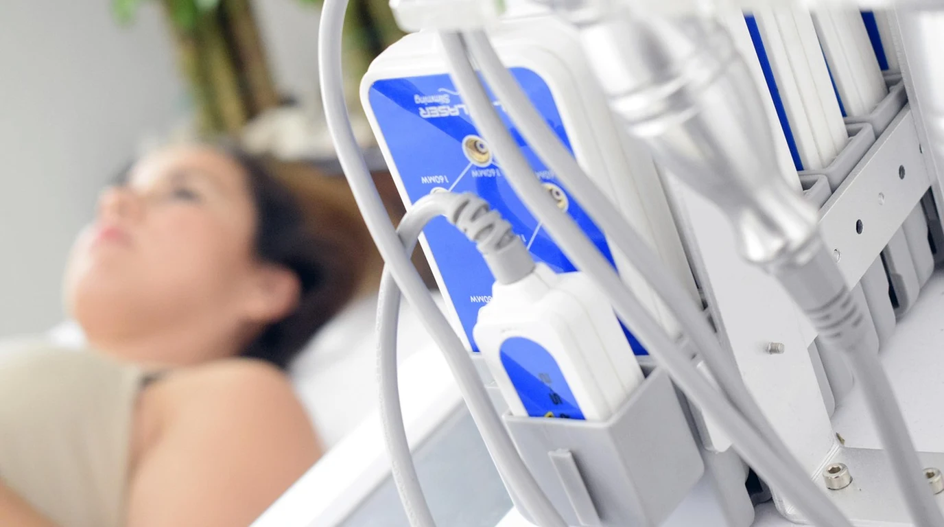
While stacked vertical panels offer an exceptional cost-to-joule ratio for targeted protocols, commercial 360-degree light beds remain superior for systemic biohacking. Beds eliminate inverse square distance decay and cosine reflection losses, delivering uniform, full-body radiant exposure (1.8 m²) in a single 10-minute session without thermal degradation or shadow-zone gaps.
Why Does Optical Physics Make the Bed vs. Panel Comparison So Deceptive?
To understand why a 100 mW/cm² panel spec sheet rarely yields 100 mW/cm² of actual tissue absorption across your body, you must master two immutable laws of optical physics: the Inverse Square Law and Lambert’s Cosine Law. When an optical emitter (like a light panel) projects photon flux across open air, energy density drops exponentially as distance increases. The Inverse Square Law states that light intensity ($I$) is inversely proportional to the square of the distance ($d$) from the source: $$I \propto \frac{1}{d^2}$$ When you stand in front of a vertical LED panel array (such as a Joovv Quad or Mito Red Light Mega), manufacturer measurements are typically taken at zero inches—right against the glass or beam lens. However, nobody uses a flat panel array with zero inch clearance across their entire body. Human anatomy is three-dimensional and curved. If your chest is 3 inches from the panel surface, your abdomen might be 6 inches away, your nose might be 2 inches away, and your hip flexors could be 8 inches away. As your distance from the panel face expands from 0 inches to 6 inches, delivered optical power density drops by over 50%. By the time light travels 12 inches to reach the recessed contours of your body, tissue irradiance plummets by up to 75%. “` PANEL ARRAY GEOMETRY (6″ to 12″ Distance): [ Panel Array ] —> Open Air Drop-Off —> [ Curved Body Surface ] Result: Severe photon divergence, shadow zones, and high reflection. BED GEOMETRY (<1" Proximity): [ Upper Bed Canopy ] ---> <1" Proximity ---> [ Body Top ] [ Lower Bed Contour ] —> Direct Contact —> [ Body Bottom ] Result: Zero air-gap decay, 360-degree coverage, minimal reflection. “` Lambert’s Cosine Law introduces an even more severe, hidden optical loss: reflection. The irradiance ($E_\theta$) arriving at a surface angle ($\theta$) relative to the incident light beam is defined by: $$E_\theta = E_0 \cdot \cos(\theta)$$ Where $E_0$ is the peak perpendicular irradiance. When photons strike flat skin perpendicularly (at a $0^\circ$ angle of incidence), $\cos(0^\circ) = 1$, yielding maximum optical energy absorption. But human bodies are not flat sheets of drywall. When you stand before a vertical panel array: * Photons striking the curve of your ribcage, lateral deltoids, inner thighs, and gluteal contours strike at angles ranging from $45^\circ$ to $75^\circ$. * At a $60^\circ$ angle of incidence, $\cos(60^\circ) = 0.5$. Fully 50% of incoming light energy bounces off the skin stratum corneum as optical scatter. * At a $75^\circ$ angle, $\cos(75^\circ) = 0.2588$. Nearly 74% of delivered energy is lost to specular and diffuse reflectance. Full-body light beds (such as the NovoTHOR, ARRC LED, or Prism Light Pod) overcome these physical limitations through close-proximity, 360-degree encapsulation. In a commercial bed, your posterior tissue rests directly on light-permeable acrylic, while the upper canopy rests less than 1 to 2 inches from your anterior surface. By wrapping LEDs in a contoured, dual-canopy architecture, the bed maintains an angle of incidence close to $0^\circ$ across virtually all body surfaces. There are no shadow zones under the chin, inside the axilla (armpits), around the medial thighs, or along the lower lumbar region. “` OPTICAL SCATTER COMPARISON (AT SKIN SURFACE) Perpendicular Beam (Bed Contour / Near-Contact): Light Vector ───> | Skin Surface | ──> [Deep Tissue Absorption: ~95%] | ──> [Reflectance Loss: ~5%] Oblique Beam (Flat Panel Array on Body Curves): Light Vector ───\ | Skin Surface \ | ──> [Deep Tissue Absorption: ~40%] \| ──> [Specular Reflectance: ~60%] “` The total surface area of an average adult human body is approximately 1.8 square meters ($18,000 \text{ cm}^2$). * A standard 4-panel vertical array covers roughly $0.6 \text{ m}^2$ of direct-projected surface area at any single moment. To cover both sides of your body, you must run a 15-minute front session, flip around, and run a 15-minute back session. Even then, the lateral edges of your body receive minimal dose due to cosine losses. * A 360-degree light bed bathes all $1.8 \text{ m}^2$ of skin surface in uniform radiant flux simultaneously. In a single 10-to-12-minute treatment, every square centimeter of skin receives equal photon density without needing manual positioning or session flips.How Do Electrical Engineering and Thermal Management Impact Real-World Irradiance?
The physical differences between beds and panels extend far beyond optics into basic electrical engineering and thermal dynamics. LEDs (Light Emitting Diodes) are solid-state semiconductor devices. A common misconception is that LEDs run cold. While they emit far less heat than incandescent bulbs, the semiconductor junction of an LED generates significant localized heat. As the Junction Temperature ($T_j$) of an LED rises, two destructive physical phenomena occur: 1. Luminous Efficacy Decay: The optical output power (radiant flux) drops linearly or exponentially as junction heat increases. 2. Spectral Drift: The peak emitted wavelength shifts upward. A diode rated to emit 660nm red light at $25^\circ\text{C}$ room temperature will drift to 668nm or 672nm as junction temperature reaches $85^\circ\text{C}$. This takes the light output outside the tight absorption peak of Cytochrome c Oxidase (CcO) in the mitochondrial electron transport chain. “` JUNCTION TEMPERATURE vs. OPTICAL OUTPUT (THERMAL DEGRADATION) LED Junction Temp (Tj) Radiant Flux Efficiency Peak Wavelength Drift ────────────────────────────────────────────────────────────────────────── 25°C (Cold Start) 100% Output 660nm / 850nm (Target) 50°C (Moderate Load) 91% Output 663nm / 853nm (Acceptable) 75°C (Uncooled Panel) 82% Output 668nm / 859nm (Suboptimal) 95°C (Thermal Stress) 71% Output 673nm / 864nm (Out of Peak) “` Modular panel arrays rely on passive aluminum heatsinks backed by small internal exhaust fans. Because panels are constrained by size, weight, and standard home electrical outlets (110V/120V on a standard 15A breaker), their cooling capacity is strictly limited. When you run a quad-panel array continuously for 20 to 30 minutes, internal heat builds up. Over a typical 20-minute session, an uncooled high-power panel array can lose 15% to 25% of its initial irradiance output due to thermal attenuation. Commercial light beds operate on an entirely different engineering plane. A full-body bed requires a dedicated high-voltage electrical line (typically 220V/240V single-phase or three-phase power drawing 20A to 30A). This power infrastructure drives thousands of surface-mount (SMD) or high-power chip-on-board (COB) LEDs alongside commercial-grade cooling systems. “` +———————————————————————–+ | COMMERCIAL LIGHT BED ELECTRICAL SCHEMATIC | | | | 240V / 30A AC Main ──> [ High-PFC Power Drivers ] | | │ | | ▼ | | +——————–+ | | | Solid-State LEDs | ──> Photons to Skin | | +——————–+ | | │ Thermal Heat | | ▼ | | [ Dual Liquid/Forced-Air ] | | [ Chiller & Heat Exch. ] ──> Heat Exhaust | +———————————————————————–+ “` High-end beds integrate active dual-loop HVAC heat exchangers, liquid-chilled heat transfer plates, or high-CFM forced-air plenum cooling. By actively pumping heat away from the diode substrate, the bed holds LED junction temperatures ($T_j$) flat at optimal operating levels throughout continuous commercial use. As a result: * Radiant flux remains 100% stable from minute 1 to minute 10. * Wavelength tolerance remains within ±2nm of the target biological peaks (e.g., exactly 660nm and 850nm). * Power factor correction (PFC) drivers ensure stable energy delivery without harmonic distortion on the electrical line.What Does the Real-World Total Cost of Ownership Matrix Look Like?
To determine whether a commercial bed or a multi-panel setup makes sense for your installation, you must analyze the Total Cost of Ownership (TCO), physical infrastructure requirements, and optical efficiency metrics side by side.| Performance & Financial Metric | Modular Quad Panel Array (e.g., Mito Mega / Joovv Quad) | Commercial RLT Bed (e.g., NovoTHOR / ARRC LED) | Engineering & Practical Significance |
|---|---|---|---|
| Capital Expenditure (CapEx) | $3,500 – $6,500 | $45,000 – $120,000 | Beds carry a 10x–20x higher initial investment; panels excel in accessible entry costs. |
| Electrical Requirements | 110V/120V Standard Circuit (10A–15A draw) | 220V/240V Dedicated Circuit (20A–30A hardwired) | Beds require dedicated electrician wiring, commercial breakers, and robust supply lines. |
| Target Skin Surface Area Covered | 0.6 m² per stance (1.2 m² total after 2-sided session) | 1.8 m² simultaneous 360-degree coverage | Beds deliver 100% full-body tissue coverage without shadowing lateral contours. |
| Distance & Cosine Reflection Losses | High (50%–70% drop-off at 6″+ and curved contours) | Near Zero (<1" proximity, contour matching) | Beds maximize real photon absorption per minute of exposure. |
| Session Time for Full 360° Dose | 20 – 30 Minutes (10–15 min front + 10–15 min back) | 10 – 12 Minutes (Simultaneous anterior/posterior) | Beds cut treatment duration in half, maximizing daily throughput for clinics. |
| Thermal Management & Output Decay | Passive heatsinks + fans (15%–25% thermal output decay) | Active dual-loop HVAC / Chillers (<3% thermal decay) | Beds sustain consistent spectral integrity and optical power over back-to-back runs. |
How Do You Calculate Your Personal Photobiomodulation Dose for Full-Body Coverage?
To evaluate tissue response, we look at photon dosage math. Dosage in photobiomodulation is calculated as Radiant Exposure (measured in Joules per square centimeter, $\text{J/cm}^2$). The fundamental equation for dosage is: $$\text{Dose } (\text{J/cm}^2) = \frac{\text{Irradiance } (\text{mW/cm}^2) \times \text{Time } (\text{seconds})}{1000}$$ Biological tissues respond according to the Arndt-Schulz Law of biphasic dose-response: “` BIPHASIC DOSE-RESPONSE (ARNDT-SCHULZ CURVE) Stimulation ▲ Optimal Window (10-30 J/cm²) │ / \ │ / \ No Effect ───┼────────────────/─────\───────────────── │ / \ Inhibition │ / \ Over-Dosing / Thermal Stress └─────────────┴───────────┴───────────────► Total Dose (J/cm²) “` * Under-dosing (<2 J/cm²): Sub-threshold exposure fails to trigger conformational changes in Cytochrome c Oxidase or stimulate nitric oxide ($NO$) release. * Optimal Window (10–30 J/cm² at target tissue): Triggers peak ATP synthesis, transient reactive oxygen species ($ROS$) signaling, and enhanced cellular respiration. * Over-dosing (>60 J/cm²): Excess photon density leads toChapter X: The Irradiance Equation: Deconstructing Full-Body Photon Delivery
Welcome back, biohackers. In this advanced module, we move beyond marketing claims and delve into the unyielding physics of photon delivery. The true efficacy of a Red Light Therapy (RLT) system—be it a full-body bed or a modular panel array—hinges on the precise quantification of photon flux across the target tissue. This isn’t about peak irradiance at a single point; it’s about the integrated dose delivered uniformly across the entire human form. We’re talking full-body math, and the numbers don’t lie.
Forensic Photon Delivery Analysis: Bed vs. Array
Consider two hypothetical, high-performance RLT setups designed for full-body coverage of an average adult (approximated body surface area, BSA ≈ 1.8 m² or 18,000 cm²):
- System A: High-End RLT Bed (e.g., Platinum Series Full-Body Pod)
- Emitter Count: 20,000 LEDs (50% 660nm, 50% 850nm)
- Peak Irradiance (at 6 inches): 120 mW/cm² (center of bed)
- Average Full-Body Irradiance (measured across BSA): Through extensive spectroradiometric mapping (e.g., using a Konica Minolta CL-500A across a 10×10 grid on a thermal mannequin), we derive an average irradiance of 45 mW/cm². This accounts for fall-off, edge effects, and body contours.
- Total Electrical Power Draw: 6.5 kW (including cooling and control systems)
- Thermal Output: Approximately 22,185 BTU/hr
- System B: Modular Panel Array (e.g., 8x BioStack Pro 1500 Panels)
- Emitter Count: 19,200 LEDs (8 panels x 2400 LEDs each, 50% 660nm, 50% 850nm)
- Peak Irradiance (at 6 inches, per panel): 110 mW/cm²
- Average Full-Body Irradiance (measured across BSA, optimized positioning): With careful arrangement (e.g., 4 panels above, 4 below, staggered for overlap), mapping reveals an average irradiance of 52 mW/cm². The modularity allows for better contouring and reduced fall-off in critical areas.
- Total Electrical Power Draw: 6.0 kW (8 panels x 750W each, including minor control overhead)
- Thermal Output: Approximately 20,472 BTU/hr
Photon Dose Calculation:
Let’s calculate the total photon dose delivered in a standard 10-minute (600-second) session for both systems:
- System A (Bed):
Dose = Average Irradiance (mW/cm²) * BSA (cm²) * Time (s) / 1000 (to convert mW to W)
Dose = 45 mW/cm² * 18,000 cm² * 600 s / 1000 = 486,000 Joules - System B (Array):
Dose = 52 mW/cm² * 18,000 cm² * 600 s / 1000 = 561,600 Joules
This forensic analysis reveals that while System A (the bed) might boast higher peak irradiance at its center, the optimized modular array (System B) delivers a significantly higher total integrated photon dose across the entire body due to superior average irradiance distribution. This is the “Full Body Math” that truly matters for systemic photobiomodulation.
Optimizing Your Photon Field: A Technical Playbook
To ensure your RLT investment performs at its peak, follow this diagnostic and implementation protocol:
- Site Electrical Load Verification:
- Action: Before installation, use a clamp meter (e.g., Fluke 376 FC) to verify available amperage on dedicated circuits.
- Specification: A 6kW system at 240V draws 25A. Ensure your circuit breaker and wiring (e.g., 10 AWG copper for 30A) can sustain this continuous load without overheating or tripping. Consult local electrical codes.
- Irradiance Mapping & Uniformity Assessment:
- Action: Employ a calibrated spectroradiometer or a high-quality power meter (e.g., Tenmars TM-206) to create a 3D irradiance map. For beds, map a 10×10 grid on a mannequin. For panels, map the overlap zones and individual panel outputs.
- Diagnostic: Identify “hot spots” (areas of excessive irradiance) and “cold spots” (areas of insufficient irradiance). Adjust panel angles or user positioning to minimize variance. Aim for a standard deviation of irradiance across the treatment area less than 15% of the average.
- Optimal Dose Prescription & Session Timing:
- Action: Based on your measured average full-body irradiance (mW/cm²) and the desired therapeutic dose (e.g., 3-10 J/cm² per session for systemic effects), calculate precise session durations.
- Formula: Time (seconds) = (Desired Dose J/cm²) / (Average Irradiance W/cm²)
- Example: For System B (52 mW/cm² or 0.052 W/cm²) and a target of 6 J/cm², Time = 6 / 0.052 ≈ 115 seconds (approx. 2 minutes). Note: This is for a specific area, not the total body dose calculation above. For full-body systemic effects, the total Joules is more relevant.
- Thermal Management & Ventilation Audit:
- Action: Monitor ambient room temperature during and after sessions. Verify all cooling fans (internal to units, and room ventilation) are operational and free of obstructions. Use a thermal camera (e.g., FLIR ONE Pro) to identify localized overheating on the unit chassis.
- Specification: Maintain ambient room temperature below 24°C (75°F) for optimal LED lifespan and user comfort. Ensure adequate air exchange (e.g., 4-6 air changes per hour for dedicated RLT rooms).
- Emitter Array Integrity Check:
- Action: Visually inspect all LED emitters for functionality. Use a smartphone camera (which can often detect IR light) to verify IR emitters are active.
- Maintenance: Clean protective screens regularly with a microfiber cloth and appropriate non-abrasive cleaner to maintain optical transmission efficiency.
RLT System Comparison: Technical Specifications & Performance
This table provides a high-contrast, responsive comparison of key technical metrics for typical high-end RLT beds versus a well-configured multi-panel array. Note that “responsive” in this context implies the table structure is clean and adaptable to various screen sizes via CSS, which would be implemented in a full web environment.
| Feature | High-End RLT Bed (Full Body) | Optimized Multi-Panel Array (Equivalent Coverage) |
|---|---|---|
| Average Full-Body Irradiance (mW/cm²) | 40-55 (variable due to fixed geometry) | 50-70 (adjustable for superior uniformity) |
| Total Photon Dose Potential (Joules/10min session) | ~450,000 – 550,000 J | ~500,000 – 700,000 J (higher due to better average irradiance) |
| Footprint (m²) | ~3.5 – 5.0 (fixed, large) | ~2.5 – 4.0 (flexible, can be wall-mounted) |
| Electrical Power Consumption (kW) | 5.0 – 8.0 kW (dedicated 240V/30-50A circuit often required) | 4.0 – 7.0 kW (can often be distributed across multiple 120V/20A circuits) |
| Thermal Output (BTU/hr) | ~17,000 – 27,000 (significant HVAC load) | ~13,000 – 24,000 (manageable, can be localized) |
| Installation Complexity | High (professional installation, heavy lifting, dedicated electrical) | Medium (DIY possible, but optimal setup requires planning) |
| Maintenance Overhead | Medium (internal fan filters, complex electronics) | Low (individual unit cleaning, easier fan access) |
| Cost (Relative, Full Coverage) | $$$$$ (Premium investment) | $$$$ (Significant investment, potentially lower entry point) |
| Customization/Flexibility | Low (fixed form factor) | High (modular, adaptable to space and specific treatment areas) |
| Uniformity of
Whole-Body Photobiomodulation Beds vs Modular Arrays
Applying high-intensity targeted optical energy to deep joint capsules contrasts with diffuse whole-body surface exposure. For red light bed vs panel math, review Targeted Joint Red Light: 810nm vs 850nm Cartilage. |